Body
Environment
Student Life, Housing, DPSS, ITS, Community Center, Onity
Issue
Overview of the Onity Kiosks used in Student Life residence halls and how to set up and troubleshoot them.
Resolution
Context
Onity Kiosks are used in Student Life residence halls to provide Staff Validation and PIN Code Change services for the building-specific keycards of the residents and staff. These keycards are separate and distinct from the U-M ID cards that all students, staff, and faculty have. This KB will cover how to set up and troubleshoot an Onity Kiosk.
Some important things to note before continuing:
-
Student Life Technology Solutions (SLTS) is responsible for troubleshooting the Integra software and the computer peripherals that allow Integra to communicate with the various hardware components in an Onity Kiosk.
-
ITS MiWorkspace Neighborhood IT (NIT) is responsible for installing and configuring the Integra software, troubleshooting hardware issues with the dedicated computer in each Onity Kiosk cabinet, and performing reimaging services for the aforementioned computer.
-
ITS MiWorkspace Engineering is responsible for updating and troubleshooting the build image for Onity Kiosks and will partner with NIT teams for any onsite follow-up that needs to be done with previously deployed Onity Kiosk computers.
-
Housing Security, a subsidiary of the Division of Public Safety and Security (DPSS), is responsible for troubleshooting and replacing all hardware encoder devices in each Onity Kiosk cabinet (white and black boxes).
-
Community Center staff for each residence hall are responsible for issuing residential keycards.
Preflight Checklist
The following should be done before beginning any work on an Onity Kiosk, regardless of workflow type:
-
In DCT or SwitchConf, depending on the network switch, change the kiosk's VLAN configuration from its default to one with internet connectivity enabled.
-
Internet connectivity is needed for driver installation, software updates, and running Windows Troubleshooters.
-
DCT and SwitchConf port entries have been labeled to show which ones each Onity Kiosk uses, as have corresponding device IP Address entries in BlueCat.
-
Verify that you have the following equipment or that it is already present at the Onity Kiosk you will be working on:
-
Relevant key(s) for specific building’s Kiosk cabinet
-
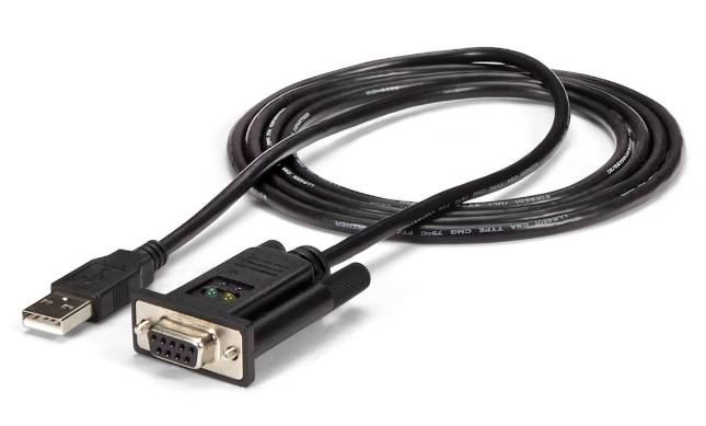
1 x USB FTDI to RS232 Serial Null Modem Adapter Cable or equivalent
-
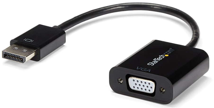
1 x 15-PIN VGA-to-DisplayPort Adapter (Female-to-Male) or equivalent
-
If replacing the Kiosk computer, turn off the computer and swap all cable connections from old to new hardware before booting.
-
For the replacement computer, ensure it has been built/reimaged with the proper build configuration and that all system updates have been applied before deployment.
-
For the legacy connection types (serial) use the adapters mentioned above.
-
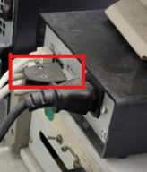
Connect the serial end of the FTDI USB to RS232 Serial Null Modem Adapter Cable to the corresponding male port on the rear of the black Onity box in the cabinet, with the USB-A end going into any available USB-A port on the rear of the PC - USB 2.0 ports are preferred as a hedge against compatibility issues, but this is not required.
-
Connect the serial end of the 15-PIN VGA-to-DisplayPort Adapter to the corresponding 15-PIN VGA-male cable from the monitor, then connect the DisplayPort end to the PC along with the touchscreen’s USB-A cable.
Setup and Configuration
-
Verify everything in the Preflight Checklist section of this KB.
-
Boot the computer
-
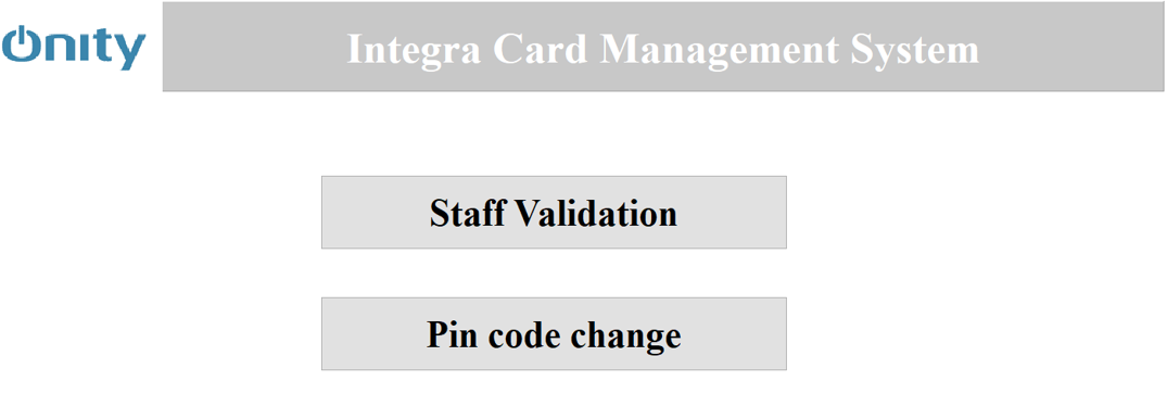
Let the computer finish initializing.
You will know this is done when the Integra software goes fullscreen and displays the Staff Validation and PIN Code Change options.
-
Once complete, log out of the default account and log in with your personal admin account.
-
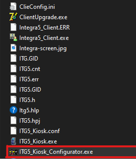
Once your desktop has loaded, navigate to the Onity program folder.
Use the USB mouse to right-click on ITG5_Kiosk_Configurator.exe and choose Run as administrator from the resulting drop menu.
-
When prompted, enter the Configurator password (reach out to SLTS if needed).

-
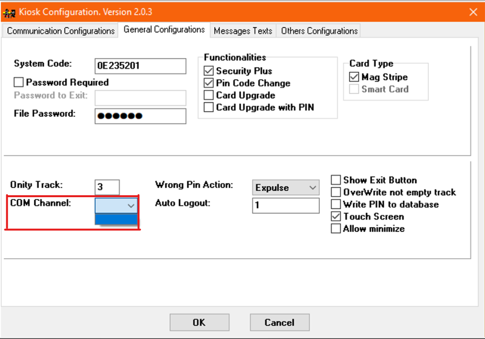
Go to the General Configurations tab and make sure the COM Channel is set to the Port matching the FTDI USB to RS232 Serial Null Modem Adapter. This information can be found in Device Manager under Ports. All other settings should be left in their default state.
-
Reboot the computer.
-
Once the Kiosk has finished loading, select either of the listed options (Staff Validation or PIN Code Change) and then tap the screen to continue. If you don't receive an “encoder error” message, you've replaced the hardware successfully.
Troubleshooting
-
Offline error messages
-
Verify network connectivity
-
Encoder error messages
-
Encoder accepts but does not return the residence card (stuck in the white encoder box)
-
Touchscreen is blank or uncalibrated
-
Check video and USB connections
-
Run the calibration executable on the computer’s desktop
-
Touchscreen needs replacing
-
Computer needs to be replaced
Additional Information
A more detailed version of this document that includes privileged information, such as passwords and file paths for the relevant sections, is maintained by SLTS. If needed for troubleshooting purposes, the applicable team may contact SLTS for a link to this document - please note this aforementioned document is not to be made available to the general public.